


From the wall socket to the sheet: what really happens inside a fiber laser source
Everyone knows a fiber laser cuts steel. Far fewer know what happens in the few meters, and the few microseconds, between the power supply and the melting point.
Understanding it is not an academic exercise: it is what lets you read a spec sheet without stopping at the kilowatt number.
An acronym that already explains half the mechanism
LASER stands for Light Amplification by Stimulated Emission of Radiation. The interesting part is "stimulated emission."
In a light bulb, atoms emit photons whenever they happen to: random directions, random phases, wavelengths spread across a broad spectrum. The result is light that scatters everywhere and cannot be concentrated beyond a certain limit.
Stimulated emission does the opposite. A photon passing close to an already excited atom prompts it to release a second photon identical to the first: same wavelength, same direction, same phase. One becomes two, then four, then an avalanche. That coherence is the real reason a laser beam can be focused onto a spot a few tens of microns across. A 10 kW industrial floodlight, by comparison, will not even scorch a sheet of paper.
Everything else, the source, the fiber, the cutting head, is engineering built around this principle.
Stage 1: pump diodes, where electricity becomes light
The chain begins with the pump diodes, semiconductor lasers that convert electrical current directly into photons, typically around 915 or 976 nm.
This is where much of the machine's overall efficiency is decided. According to data published by source manufacturers, ytterbium fiber laser sources reach a wall-plug efficiency, the ratio of optical power out to electrical power in, on the order of 30 to 45%. The most recent series go beyond 50%. A CO₂ source of the same power, by comparison, typically stops at around 10%.
That difference is not only about the utility bill. Less energy lost as heat means smaller chillers, less thermal inertia, fewer components that can drift over time.
Diodes are not eternal, but their service life is measured in tens of thousands of hours. They are, in practice, the source's "slow consumable."
Stage 2: the active medium, or why the light does not escape the fiber
The diode light is injected into a special optical fiber. It is not telecom fiber: it is a fiber doped with ytterbium (Yb³⁺), a rare earth element that absorbs the pump photons and re-emits them at a slightly longer wavelength, typically 1060 to 1080 nm.
The fiber is built in concentric layers:
- the core, the doped silica center where amplification takes place, with a diameter ranging from a few microns to a few tens in high power fibers
- the cladding that surrounds it
- the outer protective coatings
The key point is that the core has a higher refractive index than the cladding. When light traveling in the core meets the interface below a critical angle, it does not pass through: it is reflected entirely. This is total internal reflection, the same effect that makes it impossible to see out of a swimming pool when you look at the surface from below at a shallow angle.
The beam therefore stays trapped in the core along the whole length of the fiber, tens of meters coiled into a few cubic decimeters, bouncing through what you can picture as a tunnel of mirrors. It is exactly this enormous interaction length, spread over a tiny cross section, that makes active fibers so efficient. Amplification happens along the entire path, without the critical mirror alignment that open cavity sources require.
Industrial sources use double-clad fibers: the pump light travels in the inner cladding, which has a much larger cross section and therefore accepts light of poor optical quality, while the amplified signal, the good one, stays confined in the core. It works like a funnel: raw energy in, coherent energy out.
Stage 3: the cavity, without mirrors
A laser needs a resonant cavity to bounce the light back and forth through the active medium. In fiber sources this job is not done by mechanical mirrors but by Bragg gratings written directly into the fiber (FBG): periodic micro-modulations of the refractive index that selectively reflect a single wavelength and let everything else through.
The practical advantage is substantial: no optical element to align, nothing to adjust on the machine, no drift from vibration or thermal expansion. The cavity is literally inside the glass. That is why a fiber laser source behaves like a sealed component rather than an optical instrument that needs servicing.
For higher powers there are two routes, often combined: merging the output of several fiber modules into a single beam through a combiner, or adopting a MOPA architecture (Master Oscillator Power Amplifier), where a low power oscillator sets the beam characteristics and one or more fiber amplifier stages raise the power without degrading its quality.
Stage 4: from delivery to focusing
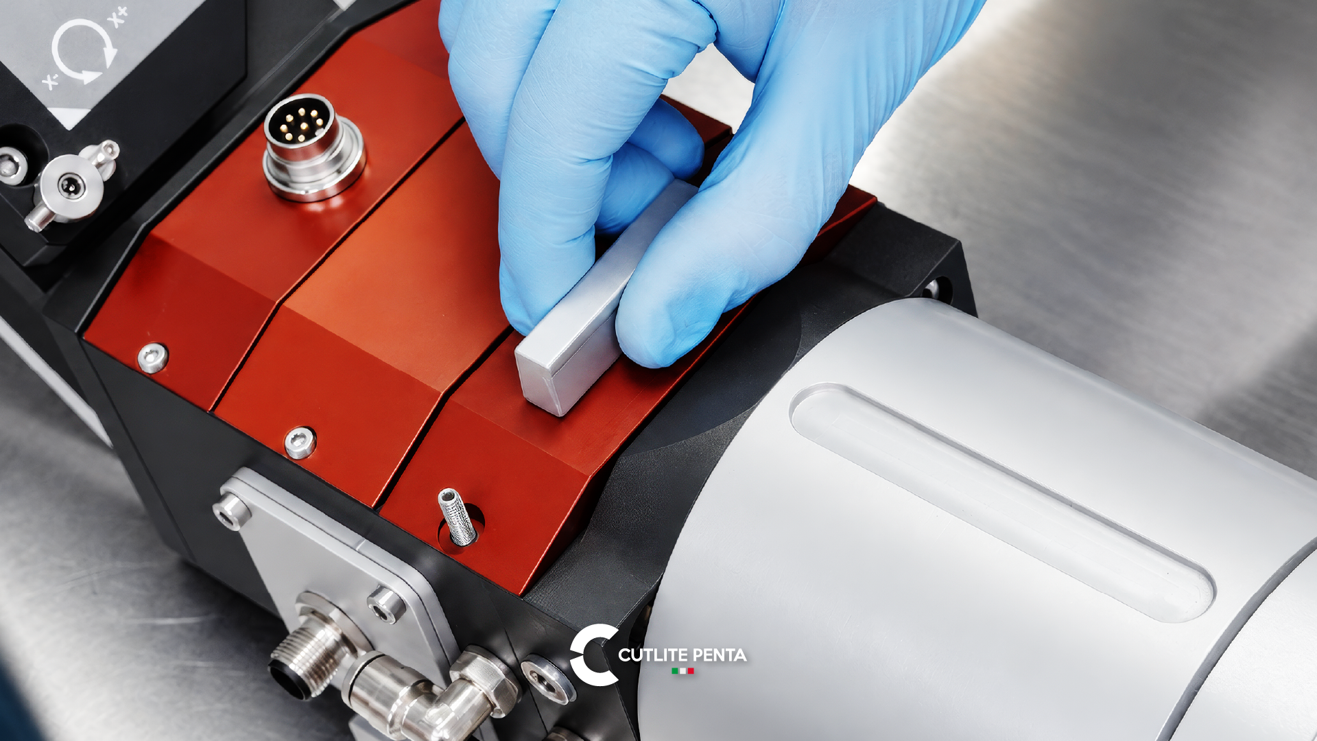
The light produced is delivered to the cutting head through a process fiber, with a core diameter commonly between 50 and 200 µm. It is one of the most underrated parameters when choosing a machine: it directly affects the minimum spot size, and therefore the balance between fine cutting on thin material and capability on thick.
At the fiber output the beam is divergent. Before it can be used it has to be straightened out, and that is the job of the collimating lens, which makes the rays parallel to one another. Only then can the focal lens concentrate them onto a single point on the sheet.
Two quantities describe beam quality along this optical chain:
- M² (beam quality factor), which measures how far the beam departs from the ideal Gaussian case
- BPP (Beam Parameter Product, in mm·mrad), which links spot size to divergence
The lower the BPP, the tighter the spot you can obtain with the same optics, and therefore the higher the power density. This is where you reach the number that actually matters. A few kilowatts concentrated on a circle 100 µm across produce power densities on the order of tens of millions of watts per square centimeter. No metal withstands that heat flux: it melts and partly vaporizes almost instantly.
Why the beam is invisible (and why that matters for safety)
At 1070 nm a fiber laser emits in the near infrared, beyond the upper limit of human vision, which stops at around 700 nm. The beam, literally, cannot be seen.
The blinding light you watch during cutting is not the laser: it is plasma and incandescent molten metal, the luminous by-product of the process. It sounds like trivia and it is in fact a matter of operational safety.
1070 nm falls inside the so-called retinal hazard region (400 to 1400 nm): the cornea and lens are transparent at that wavelength and focus it onto the retina, concentrating the energy further. A beam reflected off a shiny surface gives no visual warning and does not trigger the blink reflex, which only responds to visible light. And at these powers you do not need the direct beam: for a Class 4 source, the highest in the IEC EN 60825-1 classification and the class of every industrial cutting source, even a diffuse reflection can be dangerous.
This is why machines are designed so the operator never meets the beam: an enclosure with viewing panels certified for the wavelength, door interlocks, source shutdown on opening. That is how a system built around a Class 4 source can work on the shop floor as a Class 1 machine, safe in normal use with no additional protection.
Where full shielding is absent, during maintenance, setup or trials, personal protective equipment is required: eyewear certified for the specific wavelength (EN 207 marking in Europe) with an optical density rating suited to the power. Generic safety glasses do not protect: they attenuate visible light, not the infrared you cannot see.
From beam to cut: the last centimeter
One detail explains much of this technology's industrial success: at 1 µm, metals absorb energy far better than at 10.6 µm, the CO₂ wavelength. The difference is especially pronounced on copper, brass and aluminum, materials that were historically difficult and are now routine.
The focused beam melts the material in a minimal volume; the assist gas delivered coaxially does the rest: pressurized nitrogen to expel the melt and obtain oxide free edges, oxygen to exploit the exothermic reaction on thicker carbon steel. The width of the kerf stays in the range of tenths of a millimeter. The heat affected zone is small, because the energy is deposited in an extremely localized way and for a very short time.
Why it is worth knowing
Knowing the chain, from the pump diodes to the active fiber, from the cavity to collimation, through to focusing and the interaction with the material, changes the way you assess a system. Two "6 kW machines" can behave very differently depending on BPP, on the diameter of the process fiber, on the thermal management of the optics, and on how the control modulates power during piercing and in tight radii.
Kilowatts are the headline. Beam quality and process control are the story.
At Cutlite Penta we design and build laser cutting systems since 1992, pairing sources from the world's leading manufacturers with our own cutting head, the EVO 4, and process control developed in house.
Discover what a Cutlite Penta fiber laser can do for your production
Tell us about your work: we'll help you find the laser system best suited to your thicknesses, volumes and goals.
